
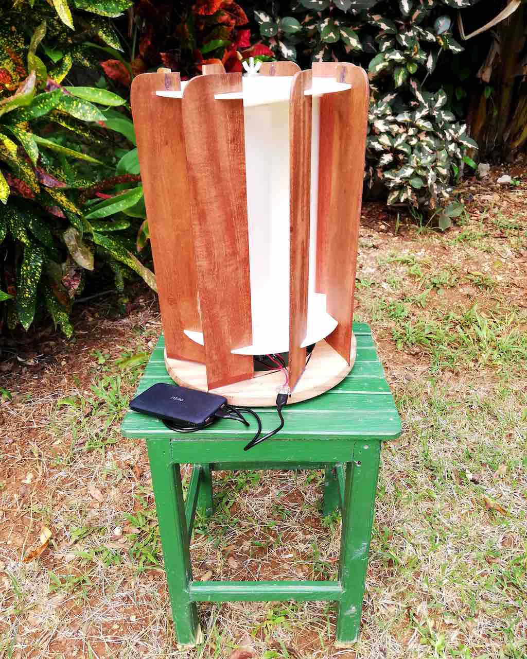
In this tutorial we will learn how to build a portable vertical axis wind turbine that can charge small electronics and power LED lights using the power of the wind. Although its power is limited, around 3 or 4W, it is an excellent starting point for experimenting with renewable energy production technologies.
Unlike horizontal axis wind turbines, which are more popular due to their high efficiency in generating electricity, they have some disadvantages. They require higher wind speeds to operate and should be installed on tall towers in flat areas to prevent trees from obstructing airflow and causing turbulence at varying speeds.
In contrast, Savonius generators have lower efficiency, but perform better at lower wind speeds and are not sensitive to wind direction or sudden changes in direction.
Contents
Materials – Tools Savonius Portable Vertical Axis Windmill
The tools and materials we will need for this project are:
- PVC tube 30 cm long and 11 cm outside diameter.
- 1950 cm2 of 4.5 mm thick Plexiglas.
- 8 wind deflectors made of rectangular boards 40 cm long by 10 cm wide and 5 mm thick.
- A circular wooden base 32 cm in external diameter and 20 mm thick.
- Threaded rod M4 length 42 cm (option A)
- Two M4 screws 6 cm long (option B)
- Eight M4 nuts
- Four 35mm long M3 screws (to extend the ones included in the stepper motor).
- Four 20mm long wood screws, no more than 4mm outside diameter.
- Four 608RS bearings
- A piece of flexible silicone tubing, 4mm inside diameter and about 6cm long.
- A Nema 14 or 17 stepper motor
- Two full-bridge rectifier modules.
- A female USB connector.
- An electrolytic capacitor.
- An LV7805 linear regulator
- A heat sink with TO-220 package (optional).
- A pair of cables for electrical connections (about 30 cm).
- sandpaper number 120
- Instant glue.
- pvc glue
- Hot silicone glue.
- Permanent marker.
- Soldering iron and tin.
- CNC machine, laser cutter, 3D printer or hire this service online
- Jigsaw.
- Disc sander.
- Saw bench.
- Angle grinder.
- Ruler and measuring tape.
- Two M10 metric wrenches
- Electrical wire stripper.
- Multimeter.
Instructions.
Step 1: Obtain the PVC pipe halves that will form the Savonius rotor.
It is necessary to cut a length of 30 cm from the PVC pipe so that the cuts are straight with respect to the surface of the pipe.
If you have flexible tape, lay it out so that it fits snugly over the surface of the pipe, using a marker draw a line that covers the entire perimeter of the PVC pipe using the soft ribbon outline. A sheet of paper can also be used for this operation.

If the hose is new and the end has been cut off at the factory, enjoy.
Using the previous line as a reference, measure 31-32 cm lengthwise and make a new mark (line) there.

Using an angle grinder and a cut-off wheel suitable for PVC, make the cuts on the previously drawn lines. Cuts should be as straight as possible. Don’t worry if they have small imperfections. The extra centimeter will allow us to sand down any imperfections until they measure 30 cm.
Using a ruler or a 90 degree angled section, fit it to the outline of the pipe and draw a horizontal line across the section of pipe you just cut. From this line, measure 172.7mm along the outline of the pipe and make a new mark at each end of the pipe. Draw a line through these new marks. Cut the tubing at these marks. At the end of this step, you should have two halves of the PVC pipe. Finally, sand down any imperfections in the cutouts.
Step 2: Cut and glue the pieces that will form the Savonius rotor
From vector drawings or files for 3D printing, cut or print these parts. In this case, it was specially designed to be cut on a CNC machine. Several parts were designed to then be assembled and glued with PVC glue. This is a major complication but a solution had to be found.
In this particular case of cut pipe sections, they must be well fixed to their support bases and in the correct position. Help yourself to the crevices created for this purpose. Important aspect, these bases must be parallel to each other once glued. Use threaded rod and nuts to securely fasten the assembly.


Something important to clarify, the design of the Savonius Rotor is mainly based on two scientific articles (1 – 2) which summarize the experimental activity and the theoretical results of various researchers.
Space, Rotor width-to-height ratio, the decision that the bases of the PVC pipe sections were closed, the angle of inclination of the wind deflectors among others are not arbitrary or random decisions, there are some scientific basis for this.
Step 3: Condition the Circular Base and Baffles
You need to make a circular hole with a diameter of 19 cm at the circular wooden base declared in the list of materials. Make a mark with a compass or similar and with the jigsaw make the cut. Leave a margin to finish with a round sander or similar.

Using the support pieces you CNC cut or 3D printed as a template, make the marks where the baffles will sit vertically. Use the table saw to make slots 5mm thick and 6mm deep. This circular piece will be the base for this entire generator set, so pay close attention to its construction.
If you prefer, you can round off some of the corners of the wooden rectangles. Make the mating slots to the deflector pieces only at the end when you have the set semi-assembled, this will avoid possible mating errors.
To help understand the assembly process of these parts, you can watch this video:
Step 4: Electrical wiring.
As you can see from the connection diagram, the interconnection of the elements that will make up the generator set is quite simple. If you’re tempted to use just one full bridge rectifier instead of two, I don’t recommend it. There may be mismatches between the voltages induced in these cables and this will cause problems (low efficiency). You can use a Schottky diode array to improve efficiency, but having these two rectifier modules will make wiring easier.

If you’re wondering what is the best type of electric motor to use as a generator, it would honestly be “the best generator should be created for this purpose alone”, but after trying various setups, the stepper motor is the one that gave the best results. . Keep in mind that the torque you are going to get with this type of machine at this scale is quite limited, the revolutions per minute are also low and directly depend on the speed and “quality” (degree of turbulence) of the wind you have in your area.
Since variations in wind speed will have a direct impact on the induced voltage, the output must be regulated to a constant voltage, in this case a 7805 type linear regulator was used which supplies 5V to the output.
Step 5: Electrical connections.
The stepper motor that was used is recycled from an old printer and comes with a pulley that had to be removed using two spanners as shown in the photo. These stepper motors will likely come with various cables. To know which wires to choose, one must measure the electrical resistance between them and select two pairs of wires with the highest electrical resistance. In this case the windings were 20 ohms and each pair had a center tap which was not used in this design.

In order to reduce the complexity for the manufacture of this generator, the electronic components have been directly soldered as shown in the connection diagram above. Before connecting the linear regulator, it is recommended to perform some functional tests.

Solder the wires to the linear regulator as shown in the diagram.
Solder the USB connector to the regulator output. You must be careful with this operation, if you have any doubts, check it here.
Only 2 wires (Vcc + 5V and Ground) will be soldered to the correct pins. To avoid compatibility issues with some devices that require data pin connections, voila!
Step 6: Fix the electronic components on their support plate and screw them to the base of the wind turbine.
It is necessary to change the M3 screws that make up the stepper motor with slightly larger screws to be able to fix it to its support plate as shown in the image. The rest of the components can be glued with hot silicone, taking care not to interfere with the rotation of the motor shaft.

For the connection of the motor shaft and the Savonius rotor, a small piece of flexible silicone tubing about 4 mm in internal diameter and about 6 cm in length was used.

The 7805 controller was also attached to the base with glue and I hot glued the USB port so it was easily accessible from the outside.
You have already assembled your Savonius Vertical Axis Portable Wind Turbine! Now all you have to do is put it to work.

Via www.instructables.com

